That moment when you’re staring at a pile of drone components with wires dangling everywhere—battery, flight controller, motors, and FPV system all waiting to be connected—feels overwhelming for first-time builders. One wrong connection can fry expensive components before your drone ever leaves the ground. Knowing how to wire a drone properly separates successful builds from frustrating failures that cost time and money. This guide walks you through every electrical connection with professional techniques that ensure reliable performance while keeping weight minimal.
You’ll discover exactly which wire gauges to use for each component, how to solder connections that survive crashes, and cable management tricks that transform messy builds into clean, flight-ready machines. Whether you’re building your first 5-inch freestyle quad or a sub-250g racing drone, these wiring principles guarantee your drone powers up correctly the first time.
Wire Gauge Selection by Application
Match Wire Thickness to Current Demands
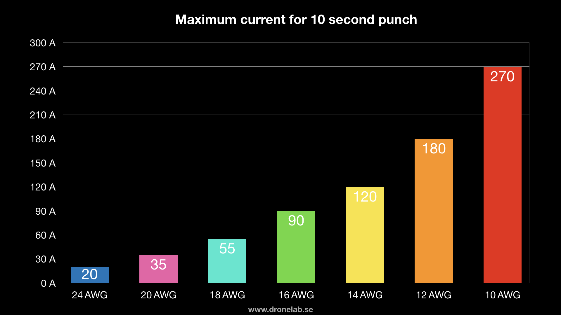
Choosing the right wire gauge prevents both dangerous overheating and unnecessary weight. For most 5-inch FPV drones running 4S or 6S batteries, 14 AWG silicone wire handles battery connections perfectly despite seeming slightly oversized—its minimal weight penalty provides crucial safety margin during 100+ amp burst draws. Smaller builds under 250 grams benefit from 16 AWG XT30 connections, which save weight without compromising reliability at lower current levels.
Critical application guide:
– 12 AWG: Best for 7-inch high-power builds or extended battery leads
– 14 AWG: Ideal standard for 5-inch frames with XT60 connectors
– 16 AWG: Perfect for XT30 connections on sub-250g drones
– 20 AWG: Required for motor extensions and signal wires
– 26-28 AWG: Use exclusively for FPV camera and receiver connections
Remember: thicker wire handles more current but adds weight. A single meter of 14 AWG weighs nearly double that of 20 AWG—every gram counts in flight performance.
Calculate Real-World Current Needs
Don’t base wire selection on average current draw—use maximum burst requirements instead. Check your motor specifications for full-throttle current and add 20% safety margin. Most 5-inch quads pull 80-120A bursts during aggressive maneuvers, making 14 AWG ideal for main battery leads. Short wire runs (under 3 inches) tolerate slight undersizing because battery limitations prevent sustained maximum current.
Pro tip: Measure actual current draw with a watt meter during bench testing. If your motors never exceed 60A in practice, 16 AWG might suffice for battery connections on smaller 5-inch builds, saving precious grams.
Connector System Strategy

XT60 vs XT30 Selection Guide
Your connector choice directly impacts reliability and weight. XT60 connectors handle 180A bursts—far beyond what any practical FPV drone requires—but add unnecessary weight to micro builds. For standard 5-inch quads, the official 60A rating provides ample safety margin while maintaining clean connections. XT30 connectors shine on sub-250g builds where every gram matters, reliably handling 60A continuous current with proper 16 AWG wiring.
When to choose XT60:
– 5-inch or larger frames
– 4S-6S battery systems
– Current draws exceeding 50A
When to choose XT30:
– Sub-250g racing drones
– 2S-3S micro quads
– Weight-critical long-range builds
Signal Wire Connection Protocol
For non-power connections like receivers and FPV systems, focus on reliability over current capacity. Cut manufacturer connectors from components and splice to your standardized system using servo or JST connectors. This approach prevents connector mismatches and ensures consistent polarity across your build fleet. Always tin both wire ends before joining—this prevents stray strands from causing shorts and creates stronger solder joints.
Professional Soldering Techniques
Achieve Flawless Solder Joints
Proper soldering separates functional builds from intermittent failures. Set your iron to 650-700°F for silicone wire—hot enough to flow solder quickly but cool enough to prevent insulation damage. Always tin wires and connector pads before joining, then heat the metal connection point (not the wire) while feeding solder into the joint. Hold steady for 2-3 seconds after solder flows, then let cool completely without movement.
Quality indicators of perfect joints:
– Shiny, smooth appearance (dull joints indicate cold solder)
– Complete wire encapsulation without gaps
– No excess solder creating potential shorts
– Minimal heat damage to surrounding insulation
Capacitor Installation Rules
Capacitors stabilize voltage but require specific wiring practices. For capacitors under 1000μF, 18-20 AWG wire works perfectly, while larger units need 16 AWG minimum. Most importantly, keep capacitor leads under 2 inches regardless of gauge—long leads defeat their noise-filtering purpose. Mount capacitors directly to battery pads whenever possible, and always secure them with hot glue to prevent vibration damage.
Clean Cable Routing Protocol

Frame-Specific Wire Management
On 5-inch frames, route battery leads along the bottom of arms and secure with zip ties every 2 inches. Motor wires should run inside frame arms when possible, taped securely to prevent vibration damage. Signal wires must stay beneath the flight controller—never route over the gyro area where electromagnetic interference causes unstable flight characteristics.
Micro drone modifications:
– Shorter wire runs possible due to compact layouts
– Prioritize weight savings over perfect routing
– Use heat shrink instead of zip ties for sub-250g builds
– Eliminate unnecessary connectors to save grams
Crash-Proof Strain Relief
Prevent crash damage from destroying your wiring with dual zip tie placement on battery leads: position one tie 1 inch from the connector and another at the frame entry point. This distributes impact forces away from solder joints. For motor wires, create small service loops near the motor mount—this 1/2 inch slack absorbs arm flexing during hard landings without stressing connections.
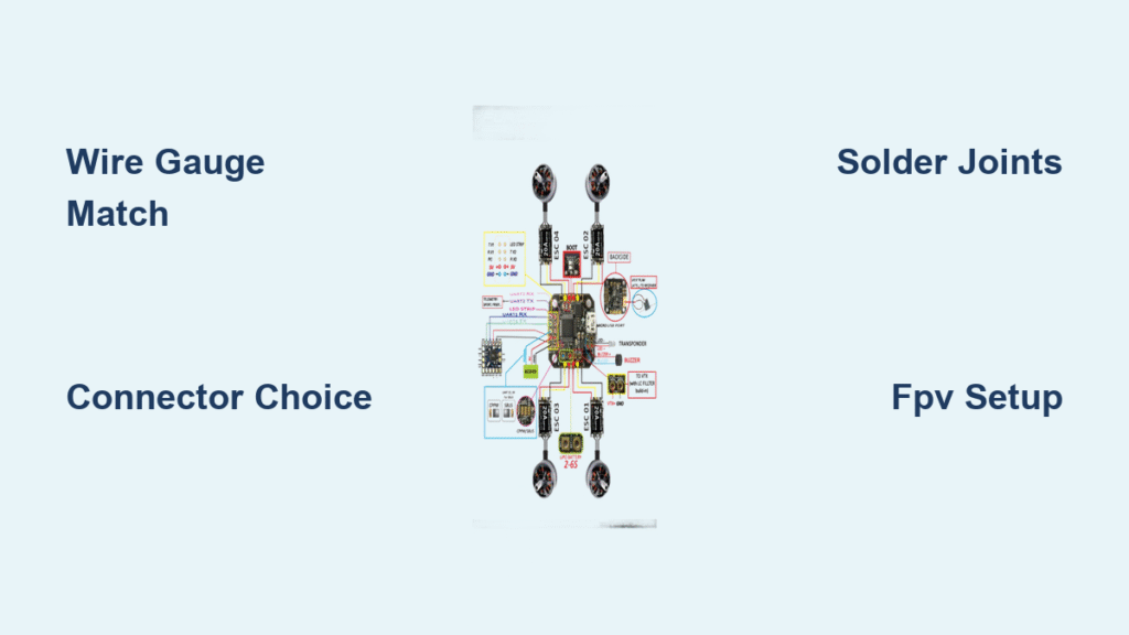
FPV System Wiring Sequence
![]()
VTX and Camera Integration
Follow this exact sequence when connecting your video system to avoid costly mistakes. Start by connecting the antenna to your video transmitter (VTX) before any other steps—applying power without an antenna destroys VTXs in seconds. Then connect battery power to the VTX’s 7-24V input, followed by the VTX’s 5V output to your camera’s positive terminal. Complete the circuit by connecting camera ground to VTX ground and video signal wire to the VTX input.
Critical Eachine TX805 wiring steps:
1. Connect antenna before any power
2. Battery positive → VTX red wire (7-24V)
3. VTX 5V output → Camera positive
4. Camera ground → VTX black wire
5. Camera video → VTX white wire
Treat your FPV system as two independent circuits: the transmitting components (camera and VTX) wired together, and the receiving components (goggles and antennas) operating separately. This prevents ground loop issues that cause video interference.
Pre-Flight Verification Checklist
Before applying power for the first time, verify these critical connections:
Essential safety checks:
– Confirm red/black polarity at every connection point
– Check for stray wire strands that could cause shorts
– Ensure all connectors are fully seated in housings
– Verify capacitor leads are under 2 inches in length
– Inspect solder joints for proper shine and encapsulation
Perform a multimeter continuity test on all power connections before first power-up. Set your meter to continuity mode and check each positive connection to its corresponding negative—there should be no continuity (open circuit) anywhere in your wiring. Then check for proper continuity along intended paths like battery to flight controller.
Common Wiring Mistakes That Ground Your Drone
Weight-Wasting Errors
New builders often add unnecessary weight through oversized wiring “just in case.” A 5-inch quad using 12 AWG where 14 AWG suffices wastes 0.8 grams per meter—seemingly trivial until you realize most builds use 15+ inches of wiring. Avoid multiple connector adapters; each adds 0.5 grams and creates potential failure points. Never leave excess wire length “for future changes”—every extra inch adds weight and increases vibration susceptibility.
Performance-Killing Oversights
Cold solder joints from insufficient heat cause intermittent failures that mimic flight controller problems. Routing signal wires over the flight controller gyro area introduces electromagnetic interference that makes your drone unstable in flight. Battery leads without proper strain relief transfer crash forces directly to solder joints, causing failures after seemingly minor impacts.
Maintenance Protocol for Reliable Flights
Inspect your wiring before every flight session. Check battery lead insulation for cuts or abrasions against frame edges, especially near arm bases. Examine connector housings for cracks or melting signs that indicate overheating. Verify signal wire routing hasn’t shifted into propeller clearance zones. Pay special attention to capacitor leads—any movement from their original position indicates mounting failure.
Carry these wire-specific spares in your field kit:
– Pre-soldered XT60 pigtail (for quick battery lead replacement)
– 6-inch lengths of 14 AWG and 20 AWG silicone wire
– Assorted heat shrink tubing (1:1 and 3:1 ratios)
– 1000μF capacitor (for emergency voltage stabilization)
Perfect drone wiring combines technical knowledge with meticulous craftsmanship. Take time with each connection—rushing leads to rebuilds that cost more time than doing it right initially. Clean routing and proper strain relief ensure your drone survives crashes and delivers consistent performance flight after flight. When you know how to wire a drone correctly, you transform a collection of components into a reliable flying machine ready for whatever the skies bring.