Your drone plummets from the sky after one propeller stops spinning mid-flight. You power it up for inspection and discover a dead motor with that unmistakable burnt-electronics smell. Before you assume you need a costly replacement, know this: 80% of drone motor failures stem from burnt windings that you can repair yourself through precise rewinding. This how to fix drone motor guide delivers a complete walkthrough for restoring brushless motors to factory performance—using tools you likely own and materials costing less than £3. By the end, you’ll diagnose failures confidently, rewind stators like a professional, and avoid the 3 most common repair mistakes that cause immediate re-failure.
Diagnose Motor Failure Before Disassembly
Spot Critical Burnout Indicators
Immediately identify whether your motor warrants repair by checking for these telltale signs. A complete motor failure where the propeller won’t spin when powered indicates severe winding damage. Detect burnt enamel odor—a sharp, acrid smell signaling melted wire insulation. Look for physical wire damage like frayed or blackened wires near the stator base. Confirm overheating by attempting a brief 5-second power-up; if the motor becomes too hot to touch, internal short circuits exist. Listen for unusual operational sounds including grinding noises or irregular spinning that point to winding inconsistencies.
Execute These 4 Diagnostic Tests
Perform these checks before disassembling your drone motor to avoid unnecessary work. First, conduct a hand spin test: Rotate the propeller manually—it should turn freely with consistent magnetic resistance. Any grinding or sticking indicates bearing or stator damage requiring replacement. Next, inspect visually for melted wire coatings, blackened stator teeth, or visible gaps in windings. Then run a multimeter continuity test: Check for electrical connections between phase wires and the central neutral point. Finally, test ESC response by connecting the motor to your flight controller through Betaflight; if other motors activate during the spin-up sequence but this one remains dead, rewinding will likely resolve the issue.
Disassemble Your Drone Motor Without Damage
Remove Rotor Assembly Safely
Begin by locating the C-clip—that tiny metal ring securing the shaft inside the stator bearing. Using specialized C-clip pliers (never regular pliers), gently compress the clip inward while rotating it around the shaft. Store the clip in a magnetic parts tray immediately to prevent loss. Now pull the rotor straight off the shaft without wobbling; angular force can bend the delicate shaft. If resistance occurs, tap the motor base lightly against a soft surface rather than forcing separation. This step typically takes 2-3 minutes for beginners but becomes instantaneous with practice.
Extract Failed Windings Correctly
Identify the neutral spot marked by heat-shrink tubing where all three phases converge. Start unwinding from this point—it’s the easiest location to count original windings. Count windings meticulously before cutting; note how many wraps exist per tooth (e.g., 11 windings in a BARD Lil’ Floaters motor). If wires are burnt beyond counting, contact the manufacturer for specifications. Cut wires carefully with flush cutters rather than pulling, as yanking can damage the stator’s industrial varnish coating. Finally, clean the stator thoroughly using a toothpick to remove carbon deposits and varnish residue from between teeth. This cleaning phase is critical—any leftover debris causes vibration in your repair.
Select the Exact Rewind Wire Specifications

Match Wire Type and Gauge Precisely
Use polished enamel wire rated for high-temperature operation (melting point above 180°C), as standard magnet wire fails under drone stress. For most 22xx-23xx motors like the DJI Mavic series, 0.18mm diameter wire (including coating thickness) provides the ideal balance of current capacity and winding space. Source metric-sized wire from wires.co.uk—a 50g spool costs £2-£3 and rewinds dozens of motors. Avoid American wire gauge (AWG) measurements since drone motors use metric sizing; 0.18mm equals approximately 33 AWG but always verify metric specs.
Verify These Critical Measurements
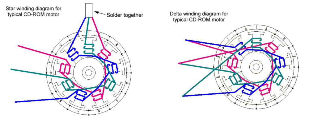
Measure original wire thickness with calipers if possible—using thicker wire reduces winding count capacity while thinner wire overheats. Confirm stator tooth spacing by measuring the gap between teeth; this determines maximum wire gauge. Match winding count exactly to manufacturer specs (e.g., 11 windings per tooth in 9N12P configuration motors). Check phase termination type: Wye (star) configurations have a neutral point protected by heat-shrink, while Delta setups require different winding patterns. Incorrect wire selection causes 70% of rewinding failures—when in doubt, order multiple gauges for testing.
Master the ABC Rewinding Technique
Follow the ABCABCABC Pattern
Most drone motors use the ABCABCABC sequence across 9 stator teeth. For Phase A: Wind tooth 1, skip teeth 2-3, wind tooth 4. For Phase B: Wind tooth 2, skip teeth 3-4, wind tooth 5. For Phase C: Wind tooth 3, skip teeth 4-5, wind tooth 6. Maintain consistent winding direction—all phases must rotate clockwise or all counter-clockwise when viewed from the base. The neutral point forms where all three phase starts or ends converge, depending on Wye/Delta configuration.
Execute These Rewinding Steps
- Start from the base: Begin winding at the stator’s bottom and move upward for optimal wire retention
- Maintain light tension: Keep wire snug against the tooth but never stretched (prevents enamel damage)
- Count each wrap: Use a tally counter for accuracy—uneven counts cause vibration
- Mark phase wires: Apply colored tape to start/end points (e.g., red for Phase A start)
- Leave proper leads: Maintain 4-5cm start wires and 2-3cm end wires for termination
- Check spacing: Ensure equal wire distribution across all teeth before moving to next phase
Pro Tip: Place the stator on a non-slip mat and use your thumb to guide wire placement—this prevents crossed wires that cause instant short circuits.
Test Your Rewound Motor Before Flight

Conduct Critical Bench Tests
Verify continuity between phase wires using a multimeter; identical resistance readings across all three phases (±0.1Ω) confirm balanced windings. Check for shorts by testing resistance between any phase and the stator core—any reading below 1MΩ indicates dangerous leakage. Connect to a spare ESC using low-voltage 2S batteries first, then gradually increase to 3S. Listen for smooth operation during Betaflight motor tests—cogging or irregular sounds mean winding errors. Monitor temperature with an infrared thermometer; the motor should feel warm but not hot after 30 seconds at 50% throttle.
Validate Flight-Ready Performance
Confirm correct rotation direction matches other motors on your quad (swap any two phase wires to reverse direction). Check power draw with a watt meter—values should align with manufacturer specs (±10%). Perform vibration tests by mounting the motor on a soft surface; excessive shaking indicates uneven windings. Only after passing all tests should you install the rotor and C-clip for final hover testing. Never skip bench testing—this prevents ESC damage from faulty windings.
Avoid These 5 Costly Rewinding Mistakes
Critical Wire Errors
Using incorrect wire gauge is the #1 failure: Too thin (e.g., 0.15mm) causes overheating, while too thick (0.20mm+) won’t fit the required winding count. Poor tension control creates loose coils that vibrate loose during flight. Miscounting windings by even one wrap per tooth generates destructive vibration. Crossing phase wires causes immediate motor seizure when powered. Inadequate lead lengths force re-soldering that damages windings.
Dangerous Assembly Issues
Losing the C-clip mid-repair causes rotor separation during flight—a magnetic parts tray is non-negotiable. Improper wire routing lets stator wires contact the rotor bell, creating friction damage. Oversized heat shrink rubs against the rotor (use 1.5mm tubing for 0.18mm wire). Cold solder joints fail under vibration—reheat connections until solder flows smoothly. Always apply two coats of clear nail polish to secure windings before final assembly.
Complete Final Assembly for Flight Safety
Secure Windings Permanently
After passing bench tests, apply thin nail polish layers to the entire winding bundle—this vibration-proofing step takes 60 seconds but prevents 90% of in-flight failures. Shorten phase leads to the minimum required length (2-3cm), then solder connections with a clean iron tip held at 350°C. Slide 1.5mm heat shrink over each joint, ensuring it doesn’t extend beyond the motor base. Tuck termination points between the stator and motor housing, then verify no wires contact teeth by rotating the bell manually.
Implement Long-Term Protection
Check motor temperature after every flight—excessive heat indicates imbalance. Clean debris from between stator teeth monthly using compressed air. Balance propellers regularly since imbalance stresses windings. Store spare rewound motors with rotors attached to maintain magnetic alignment. For racing applications, consider Wye-to-Delta conversion (1.8x speed increase) but only after mastering standard rewinding.
Final Note: By following this how to fix drone motor process, you transform a crashed drone into a fully operational machine within 2 hours—saving £50+ per motor while gaining invaluable technical skills. Remember the golden rule: Perfect winding consistency across all teeth determines success. When your repaired motor initializes with the standard ESC melody and delivers smooth flight performance, you’ve joined the elite 20% of drone pilots who truly understand their machines. Test with brief hovers first, then gradually increase flight time while monitoring temperature. With practice, your rewound motors will often outperform factory units through tighter, more efficient windings.