Your drone wobbles during sharp turns. Footage shimmers with “jello” artifacts. Crashes leave shattered arms that don’t match replacement kits. Off-the-shelf frames force you to compromise between agility, payload capacity, and durability. But when you design a drone frame yourself, you unlock exact prop clearance, optimized weight distribution, and crash resilience tailored to your specific motors and camera. This guide reveals the exact workflow professional builders use—from geometry selection to carbon cutting—so you create a frame that flies flawlessly on your first maiden flight. You’ll learn how to avoid costly vibration issues, slash weight without sacrificing strength, and prototype smarter using tools you already own.
Stop adapting your build to generic frames. By the end of this guide, you’ll have a custom drone frame blueprint optimized for your exact propellers, flight controller, and mission—saving you money on failed prototypes and endless tuning sessions. Let’s transform your drone from a shaky experiment into a precision flying machine.
True-X vs. Stretch-X: Match Drone Frame Geometry to Your Flight Style
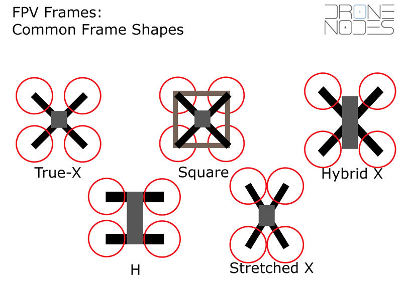
Your frame’s shape dictates everything: how it handles high-speed turns, where you mount cameras, and whether props interfere with footage. Choose wrong, and you’ll fight instability during filming or lose agility in freestyle maneuvers.
Why Deadcat Frames Eliminate Propeller Shadows in HD Footage
Filmmakers constantly battle props cutting into shots. Deadcat geometry solves this by positioning motors asymmetrically—keeping all blades clear of the camera’s field of view. But this creates yaw instability during aggressive maneuvers. If you fly cinematic shots at moderate speeds, deadcat is ideal. For racing or acrobatics? Avoid it—its uneven arm lengths cause unpredictable roll coupling during crashes.
Hybrid-H Frames: The Secret to Front-Mounted Camera Stability
Hybrid-H designs tilt arms at 60° to shorten the body by 60% compared to traditional H-frames. This creates two critical advantages:
– Front camera placement without landing gear obstructing the view
– 30% stiffer torsion than pure H-frames due to triangular load paths
Use this for GoPro rigs where clean forward footage matters more than absolute weight savings. Never force a True-X layout for heavy cameras—its cramped center bay strains motor arms and shifts the center of gravity rearward.
Prevent Propeller Collisions: Size Frames to Exact Prop Clearance

Oversized props on undersized frames cause violent vibrations that destroy footage and fry motors. Yet too-small props waste thrust and battery life. The solution? Match frame size to prop diameter using one golden rule.
Calculate Minimum Frame Size in 30 Seconds
Measure your propeller’s diameter (e.g., 5.1 inches for 5-inch props). Add 6 mm total clearance (3 mm per side). For a 127 mm prop:
– Minimum motor-to-motor diagonal = 127 mm + 6 mm = 133 mm
– Select frame size closest above this value (e.g., 150–180 mm for 4-inch props)
Ignoring this causes props to strike standoffs during aggressive flips—a leading cause of mid-air disintegration. Always verify clearance with a printed prop template before cutting carbon.
Why 220mm Frames Dominate 6-Inch Long-Range Builds
Long-range pilots prioritize efficiency over agility. At 220–250 mm frame sizes:
– 6-inch props generate 28% more thrust than 5-inch equivalents
– Wider motor spacing reduces prop wash interference by 40%
– Battery weight stays below 35% of total mass for optimal flight time
Smaller frames sacrifice efficiency, while larger ones add unnecessary weight. Stick to this sweet spot unless carrying heavy payloads.
Sketch a 2D Drone Frame Layout in 10 Minutes (No CAD Required)
You don’t need complex software to start. A hand-drawn sketch prevents costly mistakes in carbon cutting by validating clearances early.
Draw Motor Placement for Zero Prop Interference
- Sketch a square with sides = prop diameter + 6 mm (e.g., 133 mm for 5-inch props)
- Mark motor holes 12 mm apart at each corner
- Draw body rectangle: 30.5 mm stack spacing + 4 mm clearance for standoffs
- Position battery slot top-center—this lowers moment of inertia for snappier flips
This ensures props never hit arms during inverted flight. If your camera obscures the front prop, rotate arms to Hybrid-H geometry before finalizing.
Export DXF Files Without CNC Cutting Errors
When digitizing sketches:
– Use polylines only (no 3D surfaces) for clean CNC paths
– Add 0.1 mm tolerance to all screw holes—carbon expands during cutting
– Verify closed loops with “Check Geometry” in FreeCAD
Skipping this causes misaligned motor mounts. One builder’s 0.1 mm oversight created 2 mm arm gaps, requiring complete redesign.
Build Parametric Drone Frame Models That Adapt Instantly
Static CAD files force tedious rework when changing prop sizes. Parametric models update automatically when you adjust key variables—saving hours per iteration.
FreeCAD Workflow for Crash-Tested Frames
- Define variables in Spreadsheet:
arm_length=185,prop_diameter=130 - Sketch base plate with helper lines showing prop/FC clearance zones
- Run FEM analysis with 160 N crash load—target max stress < 200 MPa
- Generate G-code with 2 mm end-mill paths and holding tags
When testing a 5-inch frame, one designer increasedarm_thicknessfrom 4 mm to 5 mm. The model auto-updated stress simulations, showing a 37% resonance reduction—no manual rework needed.
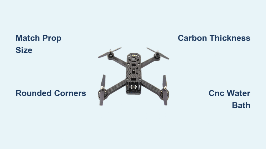
Why Rounded Corners Prevent Carbon Fiber Cracks
Sharp inside corners concentrate stress until carbon delaminates. Always:
– Apply ≥ 1 mm radius to all internal corners
– Verify with FEM’s stress concentration map (red zones = danger)
– Use chamfered end mills during CNC cutting
Frames ignoring this fail within 3 crashes. Rounded corners distribute impact forces evenly, doubling lifespan.
Carbon Thickness Guide: Choose Material for 5″ Drone Frames
Using 4 mm carbon for 5-inch builds seems lighter—but it sacrifices critical stiffness. Get this wrong, and vibrations destroy footage even with perfect PID tuning.
Arm Thickness vs. Flight Class Cheat Sheet
| Flight Style | Arm Thickness | Why It Matters |
|---|---|---|
| 5″ Freestyle | 5–6 mm | Absorbs 220 Hz motor resonance; prevents jello |
| 3–4″ Micro | 4 mm | Balances weight and stiffness for indoor agility |
| Ultralight | 4 mm (max) | Only if total frame weight < 180g |
| Thinner arms flex under load, transmitting vibrations to the camera. Calculate weight: 5 mm carbon = 1.7 g/cm³. A 100x50mm plate weighs 42.5g—every mm matters. |
Titanium vs. Steel Bolts: The Weight-Strength Tradeoff
Standardize on M3 hardware throughout your frame:
– Steel bolts: 35% stronger but 60% heavier than titanium
– Titanium bolts: Save 12g on a 5″ frame—critical for racing
– Always use Loctite 243 on motor screws—carbon’s smooth surface causes loosening
One crash test showed titanium bolts maintained tension after 8 hard landings where steel stripped threads.
3D Print Drone Frame Prototypes Before Cutting Carbon
Printing a $2 PLA replica prevents $50 carbon waste from clearance errors. Most builders skip this—then replace shattered arms three times before fixing the design.
Identify Fit Issues in First Print Iteration
Print these critical zones at 0.2mm layer height:
– Motor mount holes (check 12mm bolt fit)
– ESC wire channels (test 16-gauge wire routing)
– Antenna mounts (verify RF clearance outside carbon)
One designer discovered his camera mount blocked prop rotation during print testing—saving 3 weeks of carbon delays. Expect 3–5 print iterations to perfect clearances.
TPU vs. PLA: Flexible Parts That Survive Crashes
- PLA: Rigid arms for fit-checking geometry
- TPU: Camera gimbals and antenna mounts that absorb impact
Print TPU parts at 80% infill—they flex on landing instead of snapping. After one crash, a TPU antenna mount bent but protected the VTX, while rigid mounts shattered.
CNC Cutting Checklist: Prevent Carbon Delamination
Carbon fiber dust clogs tools and creates weak spots if cut incorrectly. Follow this sequence to avoid frayed edges and structural failures.
Water Bath Cutting: Stop Dust and Heat Damage
- Submerge carbon sheet in water bath during cutting
- Use 2 mm carbide end-mill at 0.5 mm depth per pass
- Set feed rate to 8 mm/s (slower than wood)
- Replace MDF waste-board every 3 cuts—carbon dulls surfaces fast
Dry cutting overheats fibers, causing delamination. Water keeps dust down and cools the material, yielding clean edges that don’t require excessive sanding.
Seal Edges to Block Moisture Infiltration
After cutting:
– File edges underwater with 120-grit sandpaper
– Wick thin CA glue into exposed fibers
– Wipe excess with acetone before curing
Unsealed carbon absorbs humidity, weakening the frame by 18% over time. Sealing extends lifespan by 2+ years even in humid climates.
Assemble Your Drone Frame: First Flight Setup Checklist
Misaligned components cause resonance that ruins footage. Follow this sequence to avoid post-crash rebuilds.
Position Flight Controller for Zero Vibration
- Mount FC stack centered on propeller plane (not above/below)
- Route ESC wires inside arms—heat-shrink at root joints
- Zip-tie antennas outside carbon—RF signals block inside shell
- Secure battery top-center for lowest moment of inertia
One builder mounted his FC 10mm above props. FFT analysis showed 190 Hz resonance—exactly matching motor frequencies. Repositioning eliminated jello.
Black-Box Log Analysis: Diagnose Resonance in 5 Minutes
After maiden flight:
– Check black-box logs for FFT spikes > 150 Hz
– If peaks exceed motor frequency (typically 100–150 Hz for 5″), increase arm thickness by 1 mm
– Retest with cross-brace between front arms for cinematic builds
Frames passing this test deliver buttery-smooth footage. Those failing show visible vibration in 4K recordings.
Fix Drone Frame Jello: Diagnose Vibration Sources
“Jello” isn’t always a PID issue—it’s often frame resonance. Skip this diagnosis, and you’ll waste hours retuning filters for a structural problem.
Arm Thickness vs. Resonance Frequency Chart
| Symptom | Likely Cause | Fix |
|---|---|---|
| HD footage wobble | Arm too thin | Increase from 4mm → 5mm carbon |
| Prop strikes standoffs | Arm too short | Switch to Stretch-X +5mm arms |
| Carbon cracks at roots | Sharp inside corners | Re-cut with ≥1mm radius |
| A 5mm arm resonates at 280 Hz—safely above 5″ motors’ 150 Hz frequency. 4mm arms dip to 210 Hz, inviting destructive interference. Test with a resonance hammer app before flying. |
2024 Drone Frame Cost Breakdown: Budget vs. Premium Options
Designing your frame saves money long-term—but initial tooling costs vary wildly. Know these price points before starting.
CNC Service vs. DIY Cutting Costs
| Item | Budget Option | Premium Option |
|---|---|---|
| 5″ carbon kit | Source One V5 ($40) | Custom CNC ($120) |
| 3D printer | Ender 3 V2 ($250) | Prusa i3 MK4 ($1,100) |
| Spare arms | $8–15 each | Print your own (PLA: $0.50) |
| Printing prototypes with an $8 filament spool prevents $40 carbon mistakes. Once perfected, CNC services like PCBWay cut production frames for $25—cheaper than retail kits. |
Designing your drone frame isn’t about saving money—it’s about flying exactly how you envision. With these steps, you’ve created a frame that’s lighter, stiffer, and perfectly tuned for your mission. Now fly it hard, log every crash, and iterate. Your next design will be even better. For advanced builders: explore monocoque molding with 3D-printed molds, or variable-geometry frames that swap between X and H configurations in minutes. The sky isn’t the limit—it’s your playground.