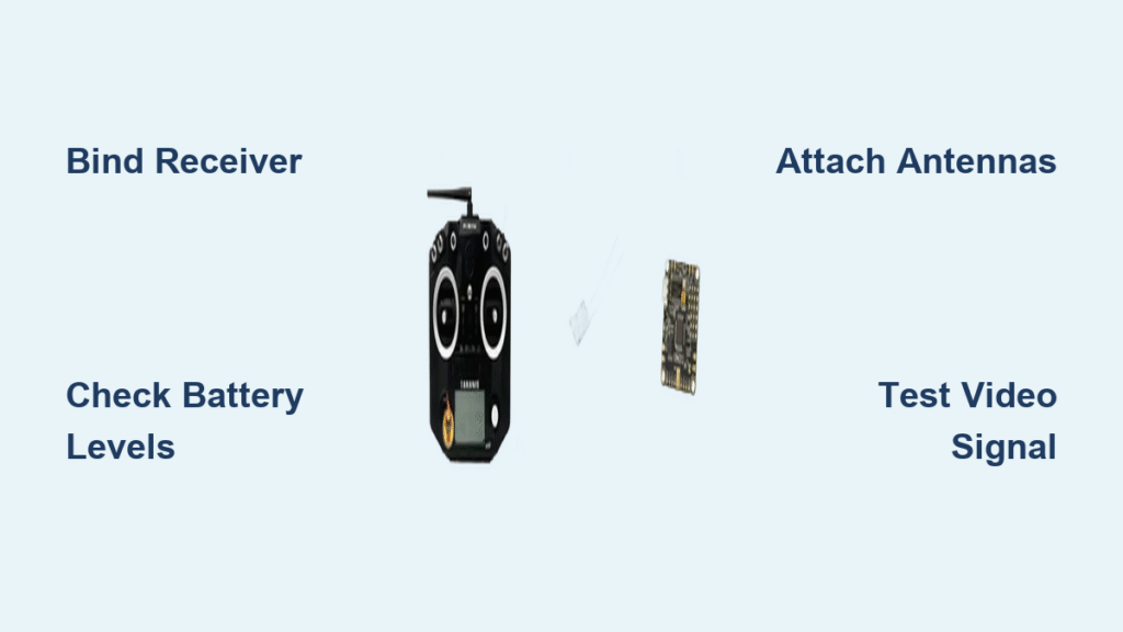
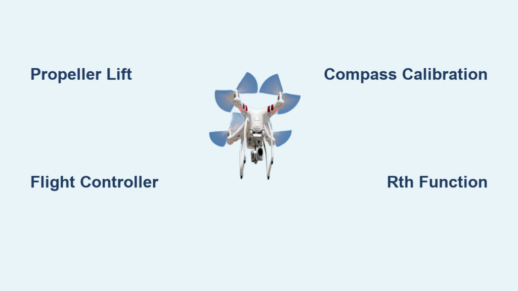
Your drone sits ready on the launch pad, but without a proper transmitter connection, it’s just an expensive paperweight gathering dust. Whether you’re struggling with radio binding or FPV video setup, this guide walks you through every connection step to get your bird airborne in under 30 minutes. Modern drones need two critical links: the control system that responds to your sticks, and the video feed that lets you see where you’re flying. Missing either connection means no flight—or worse, a crash you can’t see coming. Let’s fix both systems with proven methods for every major protocol.
Radio Transmitter Binding Process

Pre-Binding Safety Checks
Before you even touch a binding button, verify these critical safety basics:
- Battery levels: Both transmitter and drone batteries must be above 50% charge
- Firmware match: Confirm TX and RX are running compatible versions
- Physical connections: Ensure receiver properly connects to flight controller
- Props off: Remove propellers before any testing
Pro tip: Keep your transmitter manual nearby—binding button locations vary dramatically between brands like FrSky, TBS, and Radiomaster. Most beginners skip this step and waste hours troubleshooting what turns out to be a simple firmware mismatch.
Crossfire Receiver Binding
Crossfire systems prioritize range over everything else. Follow this exact sequence to bind your transmitter to drone successfully:
- Power the receiver: Connect via USB cable or flight battery
- Enter binding mode: Press and hold RX button until green LED blinks slowly
- Activate TX binding: Navigate Crossfire menu → select “Bind” on radio
- Wait for solid green: LED stops blinking when binding completes
- Allow auto-update: First connection automatically updates RX firmware
Critical warning: Interrupting the firmware update process can permanently brick your receiver. Let it finish completely—this takes 2-3 minutes depending on your system.
ExpressLRS Binding Methods
ELRS offers three distinct binding approaches for different skill levels:
Triple Power Cycle Method
- Power cycle RX three times with 1-second intervals between cycles
- Fast LED blinking indicates binding mode activation
- Run ELRS Lua script from radio’s Tools menu → select “Bind”
- Solid LED confirms successful binding
Betaflight GUI Method (ELRS 3.4+ Required)
- Connect drone to Betaflight Configurator via USB
- Navigate to Receiver tab → click “Bind Receiver” button
- Activate TX binding via Lua script
- Binding initiates automatically from flight controller
Wi-Fi Binding (Advanced Users)
- Hold RX button until Wi-Fi mode activates (fast LED blink)
- Connect to RX network (typically 10.0.0.1)
- Set binding phrase in web interface
- Save settings and restart to complete binding
Binding Verification Protocol
Never skip this step—it’s where most crashes originate. Proper verification prevents dangerous “no control” scenarios:
- USB connection: Plug drone into computer while powering receiver
- Betaflight check: Open Receiver tab → test all stick movements
- Channel response: Verify all active channels move in real-time
- Arming test: With props removed, attempt arming sequence
Red flags: No channel response, persistent blinking RX LED, or arming failures indicate incomplete binding. Return to binding steps immediately—do not attempt flight.
FPV Video Transmitter Setup

VTX to Camera Wiring Essentials
Your video system needs three connections minimum for proper operation:
Power connections:
– Battery positive → VTX power (7-24V input range)
– VTX 5V output → Camera power (when supported)
– Common ground between all components
Signal connections:
– Camera video out → VTX video in (yellow/white wire)
– Secure connections with soldering or reliable connectors
Connector choices:
– XT30/XT60 for battery power connections
– JST or GH connectors for signal wires
– Direct soldering recommended for permanent installations
Safety First: Antenna Requirements
Critical rule: Always attach the VTX antenna before powering up. Running a video transmitter without antenna load destroys the transmitter within seconds—this is the #1 cause of fried VTX units among beginners.
Additional safety checks:
– Verify voltage ratings match component specifications
– Use proper wire gauge for current requirements (18-22 AWG recommended)
– Add capacitors for power filtering if video noise appears during operation
Channel Configuration Steps
- Frequency matching: Set VTX and goggles to identical channel (use same band and channel)
- Power selection: Start at lowest power (25mW) for initial testing, increase for range
- Range testing: Walk away while monitoring video quality degradation points
- Interference check: Test near Wi-Fi routers and other 5.8GHz sources before first flight
Complete System Integration

Physical Assembly Order
Mounting sequence for optimal signal performance:
1. Flight controller with vibration dampening (use foam or rubber mounts)
2. Receiver antennas positioned clear of carbon fiber frame elements
3. VTX antenna mounted vertically for maximum range
4. Wire routing away from high-current ESC paths
Antenna positioning rules:
– Keep receiver antennas perpendicular to frame arms
– Maintain VTX antenna vertical orientation when possible
– Avoid sharp bends in coax cables (minimum 1-inch radius bends)
Final System Tests
Control link verification:
– TX range test at minimum 50 feet distance
– Stick response check in all directions and modes
– Failsafe settings programmed and tested with props removed
Video system check:
– Clear image at intended flight distance
– No video breakup during motor operation
– Channel scan shows minimal interference from other sources
Troubleshooting Common Issues
Signal loss problems:
– Check antenna connections first—they’re the most common failure point
– Verify no carbon fiber blocking antennas (carbon blocks RF signals)
– Update all firmware to latest compatible versions
Video noise solutions:
– Add LC filter to camera power line
– Route video wires away from ESCs and motors
– Use twisted pairs for long signal runs to reduce interference
Binding failures:
– Firmware mismatch: Flash matching versions on TX and RX
– Wrong protocol: Verify TX module matches RX type (ELRS vs CRSF)
– Power issues: Check battery voltage under load—not just at rest
Maintenance and Prevention
Weekly maintenance checks:
– Antenna condition and connector tightness
– Connector corrosion or looseness in all connections
– Firmware update availability for all components
– Signal strength degradation during routine tests
Before every flight checklist:
– Quick range check of both control and video systems
– Verify failsafe settings remain unchanged
– Check battery connectors for wear or damage
– Confirm channel settings match between TX and RX
Pro maintenance tip: Keep a logbook of your binding phrases and frequency settings. When you inevitably need to rebind after firmware updates, you’ll save valuable flight time by having this information readily available.
Your drone is now fully connected—from your fingertips to the flight controller, and from the camera to your goggles. Double-check your bindings, test your range thoroughly, and you’re ready for takeoff. Remember that proper transmitter to drone connection isn’t just about getting airborne—it’s about maintaining safe, reliable control throughout your entire flight. With these steps completed, you’ve eliminated the most common connection issues that cause beginner crashes, setting yourself up for successful and enjoyable flights.


