You’ve chosen Pixhawk for your custom drone build—that’s the same flight controller trusted by NASA and commercial surveyors worldwide. But staring at scattered components, it’s easy to feel overwhelmed. What motor KV matches your 4S battery? Why does compass calibration fail near your workbench? This guide cuts through the confusion with battle-tested assembly sequences and calibration protocols used by professional drone builders. You’ll learn exactly how to connect each wire, avoid deadly vibration pitfalls, and achieve rock-steady hover on your first flight.
Building with Pixhawk demands precision, but skip the trial-and-error that destroys $500 components. We’ve distilled years of field experience into this actionable blueprint. By the end, you’ll have a fully calibrated aircraft ready for autonomous missions—not just another parts collection gathering dust. Every connection, calibration step, and safety check follows the exact workflow we use for client drones in surveying and cinematography.
Essential Components Checklist for Your Pixhawk Build
Before soldering anything, verify these mission-critical parts. A single mismatched component can cause catastrophic mid-flight failure—especially with Pixhawk’s high-speed processing.
Core Flight Controller Compatibility
Pixhawk 4 handles professional workloads:
– Triple IMU sensors prevent single-point failures during complex missions
– 480 MHz processor maintains stability even with heavy camera payloads
– Operates reliably from -40°C to 85°C—critical for high-altitude flights
Pixhawk 2.4.8 suits learning builds:
– 168 MHz processor sufficient for basic stabilized flight
– Single IMU system keeps costs down for your first build
– Perfect for practicing wiring before investing in Pixhawk 4
Power System Requirements
Battery must match your frame size:
– 4S-6S LiPo (14.8V-22.2V) for multirotors—never exceed 6S on 450mm frames
– Minimum 5000mAh capacity for 15+ minute flight times
– 20C discharge rating to handle aggressive maneuvers without voltage sag
Power module non-negotiables:
– 90A continuous rating for heavy-lift configurations
– Real-time telemetry showing voltage drops under load
– XT60 connectors only—cheap clones cause melted solder joints
Frame Assembly: Preparing Carbon Fiber and Mounting Components

Inspect and Prepare Carbon Fiber
Examine every carbon fiber arm under bright light for hairline cracks—these cause sudden mid-flight disintegration. Clean mounting surfaces with 99% isopropyl alcohol to remove machining oils that prevent thread locker adhesion. Critical step: Apply medium-strength Loctite 243 to all metal screws before insertion. Carbon strips threads easily, and this prevents $200 rebuilds from loose motors.
Install Power Distribution Board
Mount your PDB using nylon standoffs, orienting XT60 connectors toward the rear for clean wire routing. Test continuity between all positive/negative pads with a multimeter—shorted power systems fry Pixhawk instantly. Solder battery connector first, then add 5V/12V BEC circuits if running accessories. Double-check polarity: reversed connections destroy ESCs in milliseconds.
Motor Mounting and Direction
Position motors using your frame’s rotation diagram—front-right and rear-left spin counter-clockwise. Test direction by connecting ESCs to battery while props are off. Pro tip: Apply thread locker but torque screws to only 0.8 Nm. Over-tightening cracks carbon fiber arms, causing dangerous wobble during flight.
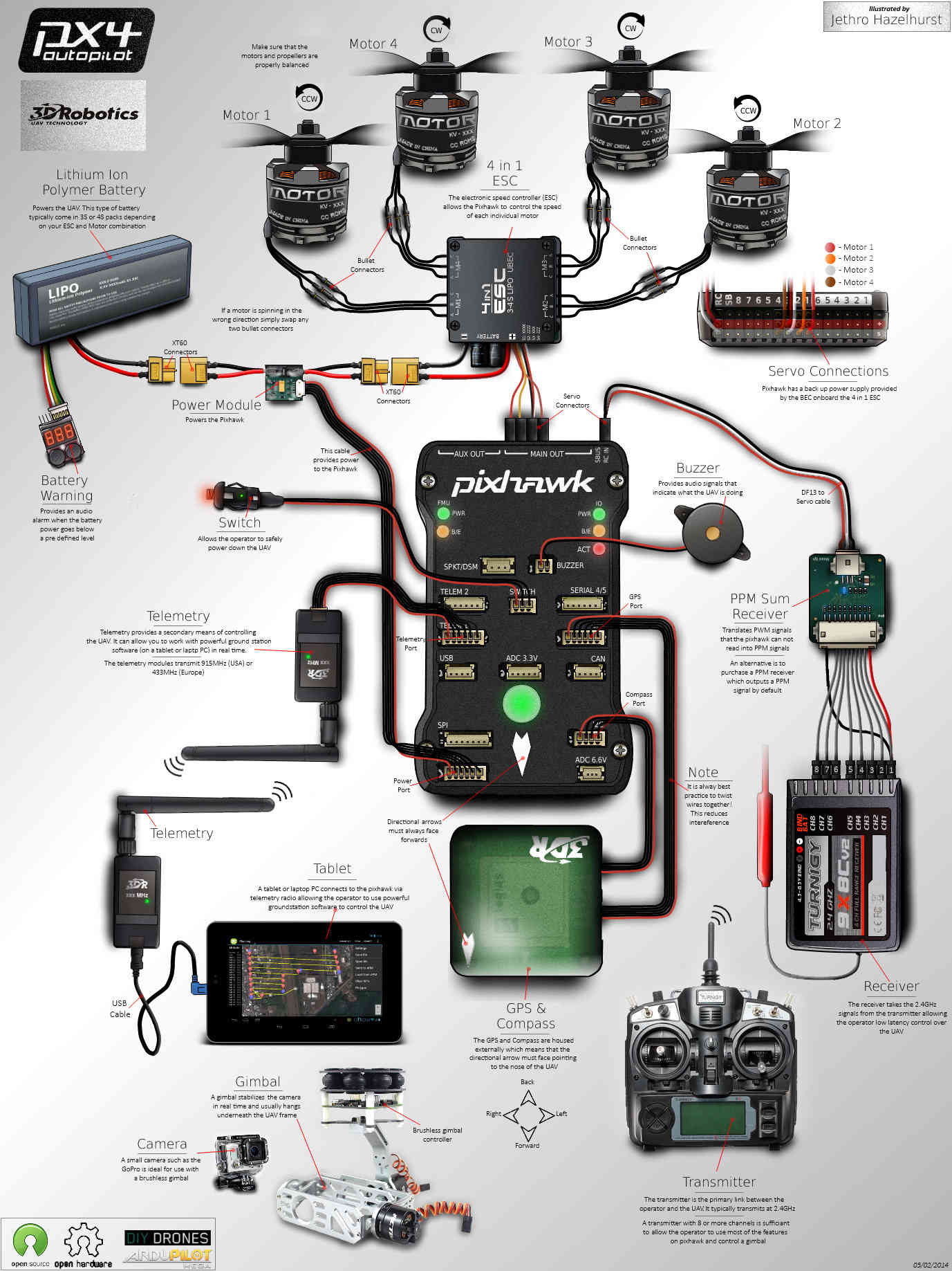
Pixhawk Flight Controller Integration: Wiring and Connections
Mounting Requirements for Vibration Isolation
Place Pixhawk on vibration-dampening foam pads with the arrow pointing toward the nose. Verify level mounting using a bubble level across the case—more than 2° tilt causes persistent drift. Ensure USB port accessibility for field firmware updates, and never mount near motors where vibrations exceed 0.5g.
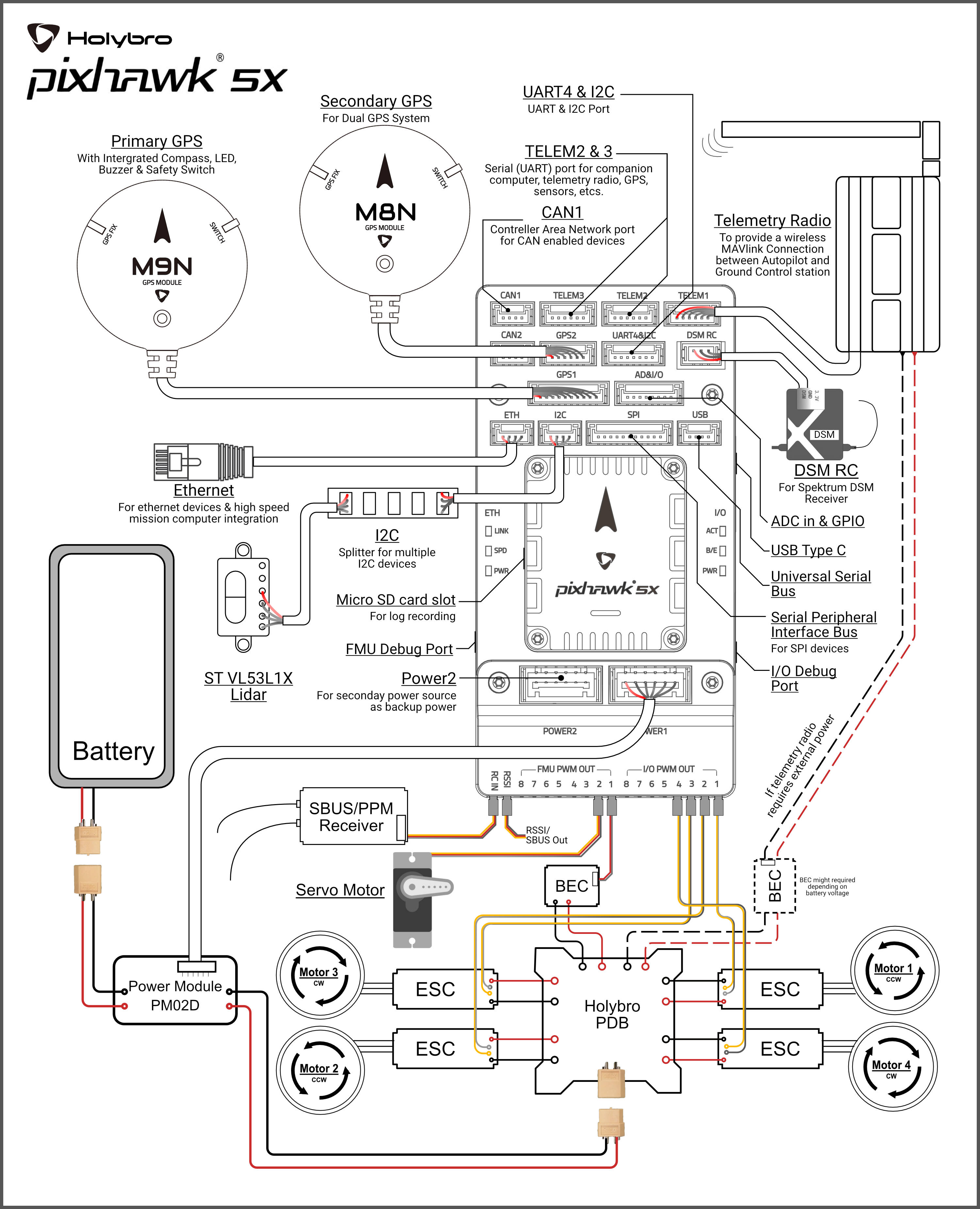
Critical Wiring Connections
Power sequence:
1. Power module → Pixhawk POWER port (6-pin)
2. Battery → Power module XT60 connector
Never connect battery before power module calibration
Signal wiring:
– ESC signal wires → Pixhawk MAIN OUT pins (Pin 1: Front right motor)
– GPS/Compass → GPS port (6-pin)
– Receiver → RCIN port (SBUS protocol preferred)
– Safety switch → SW port
Motor mapping:
– Pin 1: Front right (CCW)
– Pin 2: Rear left (CCW)
– Pin 3: Front left (CW)
– Pin 4: Rear right (CW)
Sensor Calibration Sequence: Accelerometer and Compass
Accelerometer Calibration Steps
Place your aircraft on a granite countertop or machined surface. In Mission Planner, rotate through all six cube positions—each face flat on the surface. Green indicators must confirm success for all axes. Values must read within ±0.1g; if not, vibration is contaminating sensors. Store calibration permanently in EEPROM—Pixhawk resets this on power cycles.
Compass Calibration Protocol
Perform outdoors 20+ feet from vehicles or rebar. Hold the drone and rotate through all axes until Mission Planner’s sphere fills with green dots. Achieve green status for both internal and external compasses—ignoring this causes “toilet bowl” drift. If interference persists, mount GPS on a 10cm mast above electronics.
Radio Control Binding and Setup
Bind transmitter to receiver before connecting to Pixhawk. Verify channel responses:
– Channel 1: Roll (stick left/right)
– Channel 3: Throttle (stick up/down)
– Channel 5: Flight mode switch
Set failsafe throttle to minimum position—this prevents runaway drones during signal loss.
Firmware Configuration: ArduPilot Setup for Stable Flight
Initial Parameter Setup
Select your exact frame type (e.g., “X configuration 450mm”) in Mission Planner. Configure battery monitoring matching your cell count—set failsafe at 14V for 4S batteries. Enable “PreArm Safety Check” to prevent takeoff with compass errors. Critical parameter: MOT_SPIN_ARM to 0.15 prevents motor startup until armed.
Flight Mode Configuration
Program your mode switch:
– Stabilize: Manual flight with gyro assistance (ideal for first flights)
– Alt Hold: Maintains altitude when you release sticks
– Loiter: GPS position hold for photography
– RTL: Auto return to launch at 50m altitude
Start with Alt Hold for initial tests—never use Auto mode until hovering is mastered.
PID Tuning Starting Values
For 450mm frames:
– Roll/Pitch P: 4.5, I: 0.09, D: 0.004
– Yaw P: 4.5 (increase to 5.5 for snappier turns)
– Throttle rate: 1.0
Adjust only one parameter at a time. If oscillations occur, reduce P value by 10%.
Pre-Flight Testing Protocol: From Tethered to First Flight
Hardware Verification Checklist
Before every flight:
– [ ] Propellers tight (use torque wrench set to 0.4 Nm)
– [ ] GPS lock with 8+ satellites (check Mission Planner)
– [ ] Battery voltage above 14.8V for 4S
– [ ] Compass heading matches actual orientation
– [ ] Safety switch functional
Tethered Hover Test
Secure aircraft with 2-meter tethers. Arm motors and gradually increase throttle to 30%—enough for 1-foot hover. Watch for:
– Oscillations: Indicates vibration or incorrect PID values
– Drift: Suggests compass miscalibration
– Hot ESCs: Means undersized power system
Never exceed 30 seconds in tethered tests—vibration builds rapidly.
First Untethered Flight
Choose an open field with 50m clearance. Start with 3-foot hover for 20 seconds, testing gentle pitch/roll inputs. Land immediately if:
– Battery voltage drops more than 0.5V under load
– GPS status changes from 3D to 2D lock
– Any motor runs hotter than 60°C
Your first goal is stable 30-second hover—not fancy maneuvers.
Troubleshooting Common Pixhawk Drone Problems
Power System Failures
Symptoms: Mid-flight shutdowns, erratic throttle response
– Recalibrate power module in Mission Planner (3.3V reference)
– Verify battery C-rating supports total current draw (e.g., 5000mAh needs 100A C-rating for 4S)
– Add 470µF capacitors across ESC power inputs to prevent voltage spikes
GPS and Compass Problems
Symptoms: Circular drifting (“toilet bowling”), position jumps
– Recalibrate compass away from concrete (rebar interference)
– Mount GPS on carbon fiber mast 10cm above Pixhawk
– Update to latest ArduPilot firmware (v4.4+) for improved EKF filtering
Vibration Issues
Symptoms: Video “jello,” unstable hover
– Balance propellers using a $15 magnetic balancer
– Install Pixhawk on dual-layer dampening foam
– Enable gyro notch filtering: INS_NOTCH_ENABLE = 1
– Check motor mounting bolts at 0.8 Nm torque
Maintenance Schedule for Long-Term Reliability
Before every flight, inspect propellers for micro-cracks—these cause dangerous imbalance. Weekly, check ESC temperatures after flight; over 80°C indicates undersized components. Monthly, disassemble arms to inspect for carbon fiber fatigue near motor mounts. Always store batteries at 3.8V per cell in fireproof containers—never leave charged batteries unattended.
Building your Pixhawk drone merges engineering precision with hands-on craftsmanship. Stick to this sequence: verify components → assemble frame → calibrate sensors → test incrementally. Your first hover might feel nerve-wracking, but that moment when your custom-built aircraft holds position flawlessly makes every solder joint worthwhile. Now power up Mission Planner—your autonomous flight journey starts today.