You’re standing on the field, thumbs on the sticks, watching your drone respond instantly to your commands. But have you ever wondered exactly how do drone transmitter work to make this possible? Every time you push a control stick, your radio controller converts that physical movement into precise radio signals that travel to your aircraft, triggering immediate motor responses. This invisible communication happens hundreds of times per second, creating the seamless flying experience we take for granted.
Understanding how drone transmitters work isn’t just technical trivia—it’s essential knowledge that helps you diagnose issues, extend your flight range, and make smarter purchasing decisions. Whether you’re a beginner experiencing signal dropouts or an experienced pilot pushing range limits, knowing what happens between your fingers and the propellers transforms how you fly. Let’s dive into the complete technical journey of your control inputs from transmitter to flight.
Physical Control Inputs to Digital Signals
Your drone transmitter begins its work the moment you touch the control sticks. These physical inputs undergo precise conversion before becoming radio signals that can travel to your aircraft.
Stick Movement Detection Technology
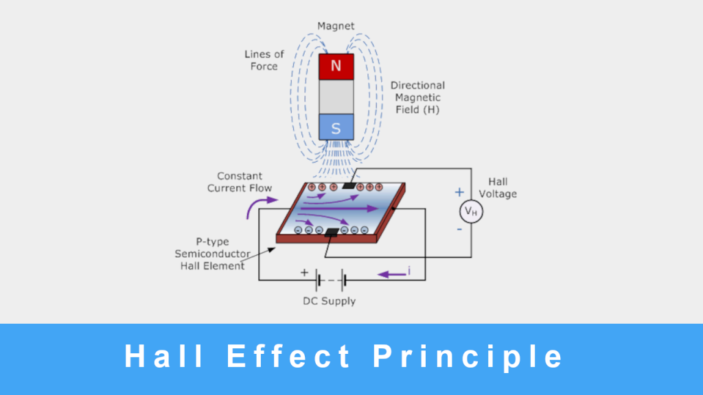
Each control stick contains sophisticated sensors that translate your thumb movements into electrical signals. Budget transmitters use potentiometer-based gimbals, where wiper contacts slide across resistive tracks to measure position. These eventually wear out, causing stick drift. Premium transmitters employ Hall-effect sensors that detect magnetic field changes without physical contact, delivering smoother operation and virtually unlimited lifespan.
When you move a stick, these sensors generate analog signals representing position between minimum (1000µs) and maximum (2000µs) values. The transmitter’s processor samples these signals at least 50 times per second, converting them into digital commands. Each axis (left/right, forward/back) consumes one channel, meaning four channels for basic flight control.
Switch and Button Functionality
Beyond the sticks, your transmitter’s switches and buttons provide critical auxiliary functions. A two-position switch typically handles arming/disarming for safety, while a three-position switch often controls flight modes (manual, angle, horizon). Momentary buttons might trigger return-to-home or emergency stops. Each of these controls consumes an additional channel beyond your basic four flight axes.
Most pilots need at least six channels: four for flight control plus arming and flight mode selection. Advanced configurations with camera gimbals or complex failsafes may require 8-16 channels. Each switch position or slider location gets encoded into the transmitter’s data stream, ready for radio transmission.
Radio Signal Transmission Process
Once your inputs become digital data, the transmitter packages and sends this information through the air to your drone’s receiver using sophisticated radio techniques.
Frequency Selection and Modulation
Most consumer drones operate on the 2.4 GHz frequency band, which offers excellent performance for line-of-sight flying up to 1-2 kilometers. This band uses Frequency-Hopping Spread Spectrum (FHSS) technology, automatically changing sub-channels hundreds of times per second to avoid interference from Wi-Fi networks or other transmitters.
For long-range applications, 900 MHz systems like TBS Crossfire and ExpressLRS provide superior obstacle penetration and extended range (10-30 kilometers). The trade-off is larger antennas and potential licensing requirements in some regions. Your transmitter encodes the control data using a specific modulation scheme before broadcasting it through the antenna.
Binding: Establishing the Secure Connection
Before your transmitter can control a drone, it must establish a unique pairing through the binding process. This one-time setup creates an exclusive communication channel between your specific transmitter and receiver. To bind, you place the transmitter in bind mode (usually through a menu option), then power on the receiver while holding its bind button. The receiver’s LED will blink rapidly during pairing, then turn solid when successful.
This binding process creates a unique identifier that prevents interference from other pilots’ transmitters. Modern systems store multiple aircraft profiles in memory, allowing you to switch between different drones instantly by selecting the appropriate model in your transmitter’s menu.
Receiver Processing and Flight Control
Your drone’s receiver completes the communication chain by translating radio signals back into actionable commands for the flight controller and motors.
Signal Decoding and Protocol Conversion
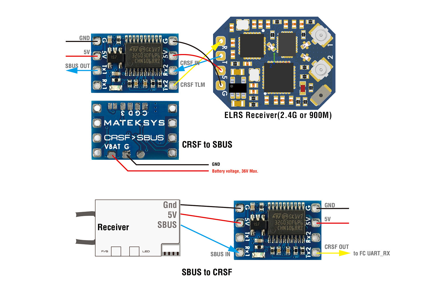
The receiver continuously scans for its paired transmitter’s unique signature, ignoring all other signals. When it detects your transmitted data, it decodes the radio signal back into digital commands representing each channel’s position. Most modern systems use protocols like SBUS, CRSF, or IBUS that deliver commands to the flight controller with minimal latency (3-5 milliseconds).
The flight controller processes these inputs alongside data from onboard sensors (gyroscopes, accelerometers, GPS), running complex algorithms to maintain stability while executing your commands. For example, when you command “roll left,” the flight controller calculates which motors need to spin faster and which slower to achieve the desired movement while maintaining altitude.
Telemetry: The Critical Feedback Loop
Modern drone systems provide two-way communication, with telemetry data flowing from the aircraft back to your transmitter. This includes battery voltage, signal strength (RSSI), GPS coordinates, altitude, and current draw. Your transmitter displays this information through visual readouts or audio alerts, allowing you to monitor critical parameters during flight.
This feedback loop enables crucial safety features like automatic return-to-home when signal strength drops below safe levels or battery voltage approaches critical levels. Most systems update telemetry data 1-10 times per second, depending on protocol and range, giving you near real-time awareness of your aircraft’s status.
Antenna Design and Range Optimization
Your transmitter’s antenna performance directly determines maximum control range and reliability—understanding the basics helps prevent signal loss crashes.
Transmitter Antenna Configuration
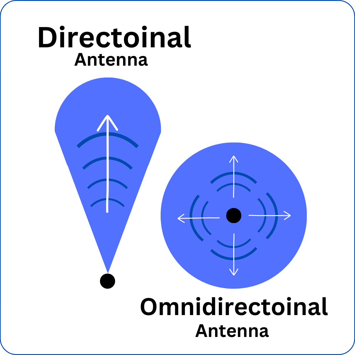
Most transmitters use external antennas with SMA or RP-SMA connectors, allowing easy upgrades. Standard antennas provide omnidirectional coverage, while higher-gain directional antennas (5-8 dBi) focus signal energy forward for extended range. The trade-off requires maintaining proper antenna orientation toward your drone during flight.
For long-range missions, experienced pilots often use patch or helical antennas that dramatically increase range in a specific direction. However, these directional antennas require careful aiming—pointing them away from your aircraft causes immediate signal loss. Always inspect your transmitter antenna for bends or damage before flying, as even minor deformations can significantly reduce range.
Receiver Antenna Placement Strategy
Drone receivers typically use two antennas mounted at 90-degree angles for diversity reception. This configuration ensures that if one antenna experiences signal blockage due to aircraft orientation, the other maintains the connection. For 2.4 GHz systems, the active element must be precisely 31mm long—damaged or shortened antennas drastically reduce performance.
Route receiver antennas away from carbon fiber frames and electronic noise sources like motors and ESCs. Secure them with heat shrink tubing to prevent propeller strikes, and ensure they’re positioned where they won’t be blocked by the aircraft’s structure during flight.
Troubleshooting Common Transmitter Issues
Understanding how do drone transmitter work enables faster diagnosis and resolution of common problems that might otherwise ground your aircraft.
Signal Loss and Range Problems
Intermittent control usually indicates antenna issues—check for bent transmitter antennas, damaged receiver coax cables, or loose U.FL connectors. Range degradation often stems from environmental factors like Wi-Fi congestion or building interference. Try changing locations or upgrading to a 900 MHz long-range system for challenging environments.
Always verify your legal power limits—exceeding regional restrictions risks fines and interference complaints. In the United States, 2.4 GHz systems are limited to 1 watt effective radiated power, while 900 MHz systems may require an amateur radio license for higher power operations.
Stick Drift and Calibration Errors
Stick drift occurs when gimbals send incorrect center positions, causing unintended movement. First, calibrate gimbals through your transmitter’s firmware menu—most systems offer automatic calibration routines. Persistent drift indicates worn potentiometer tracks (in analog gimbals) or failing Hall sensors (in digital gimbals).
Replace gimbals showing physical wear or inconsistent readings. Hall-effect gimbals offer superior precision and longevity, justifying their higher cost for serious pilots. Regular calibration prevents gradual drift accumulation that leads to frustrating control issues during flight.
Key Takeaway: Your drone transmitter functions as a sophisticated radio computer that converts physical stick movements into precise flight commands through a multi-step process of input detection, digital encoding, radio transmission, and signal decoding. Understanding how do drone transmitter work—from the gimbals in your hands to the motors in the air—empowers you to maximize performance, troubleshoot issues effectively, and fly more safely. Regular antenna inspection, proper calibration, and awareness of environmental factors ensure reliable control for countless successful flights. Whether you’re a beginner or experienced pilot, this knowledge transforms how you interact with your aircraft and enhances your overall flying experience.